


AXIS#.SM.MODE
Description
AXIS#.SM.MODE defines the mode of service motion for each loop. Two types of service motion are available:
- A constant motion in one direction (endless or for a certain amount of time).
- An alternating motion.
The service motion can be stopped by using AXIS#.STOP .
The possible modes for this parameter are described in the following table:
|
AXIS#.SM.MODE |
Description |
Requirements |
|---|---|---|
|
0 |
Continuous or pulse motion using V1, I1 and T1
|
AXIS#.OPMODE = 0,1, or 2 AXIS#.CMDSOURCE = 0 |
|
1 |
Reversing motion
|
AXIS#.OPMODE = 0, 1, or 2 AXIS#.CMDSOURCE = 0
|
| 2 |
Continuous or pulse motion using V2, I2 and T2. However, the motion is described by AXIS#.SM.I2, AXIS#.SM.T2 and AXIS#.SM.V2. This enables a change on the fly and is mostly used under fieldbus control. |
AXIS#.OPMODE = 0, 1, or 2 AXIS#.CMDSOURCE = 0 |
Profiles
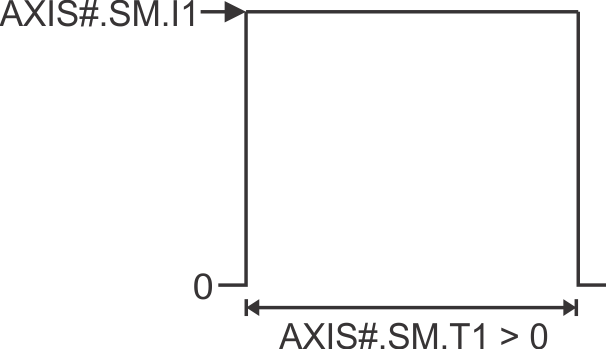
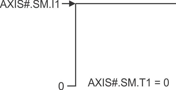
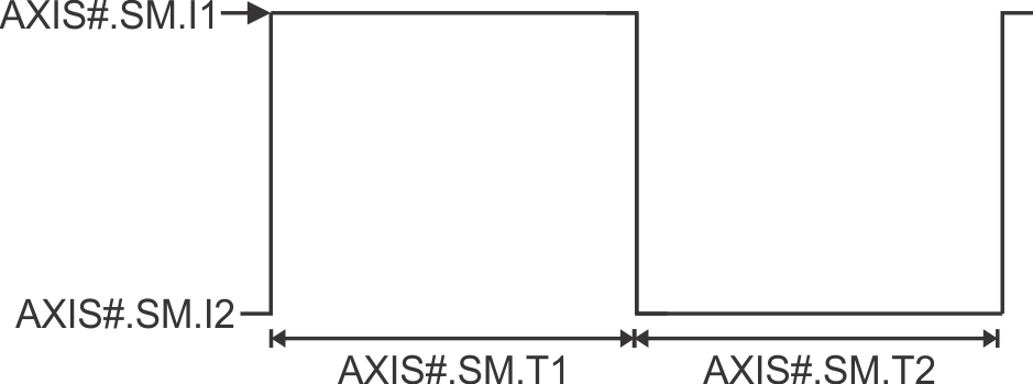
Service Motion for AXIS#.SM.MODE 0 and AXIS#.OPMODE 0 (Current)
Profile when AXIS#.SM.T1 is greater than 0:
Profile when AXIS#.SM.T1 equals 0:
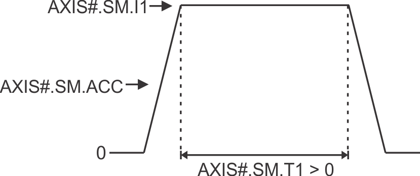
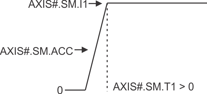
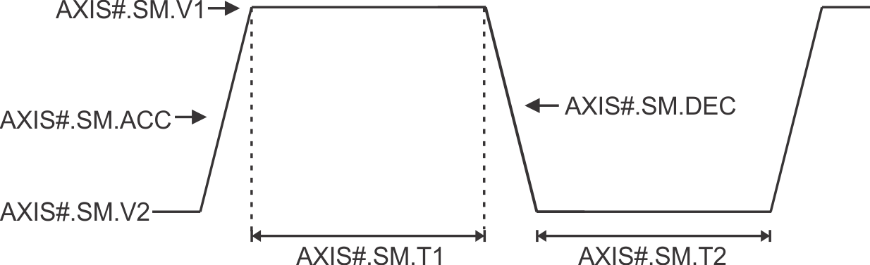
Service Motion for AXIS#.SM.MODE 0 and AXIS#.OPMODE 1 or 2 (Velocity or Position)
Profile when AXIS#.SM.T1 is greater than 0:
Profile when AXIS#.SM.T1 equals 0:
Service Motion for AXIS#.SM.MODE 1 and AXIS#.OPMODE 0 (Current)
Service Motion for AXIS#.SM.MODE 1 and AXIS#.OPMODE 1 or 2 (Velocity or Position)
Versions
| Action | Version | Notes |
|---|---|---|
| Implemented | 02-00-00-000 |
General Information
|
Type |
Read/Write |
|
Units |
N/A |
|
Range |
0 to 2 |
|
Default Value |
0 |
|
Data Type |
Integer |
|
See Also |
|
|
Stored in Non-Volatile Memory |
Yes |
Variants Supported
All variants are supported.
Fieldbus Information
|
Command |
Index |
SubIndex |
Data Type |
Units |
Float Scale |
Access |
PDO Mappable |
|---|---|---|---|---|---|---|---|
|
AXIS1.SM.MODE |
500eh |
03h |
Unsigned16 |
- |
- |
Read/Write |
No |
|
AXIS2.SM.MODE |
510eh |
03h |
Unsigned16 |
- |
- |
Read/Write |
No |
|
Name |
ID |
Hex |
Data Type |
Access |
Units |
|---|---|---|---|---|---|
|
AXIS1.SM.MODE |
6402 |
1902 |
Unsigned16 |
Read/Write |
- |
|
AXIS2.SM.MODE |
71938 |
1190 |
Unsigned16 |
Read/Write |
- |
|
Parameter |
PNU |
Data Type |
Access |
Units |
|---|---|---|---|---|
|
AXIS#.SM.MODE |
6402 |
Unsigned16 |
Read/Write |
- |


